
Products
Continuous Mechanical Flotation Cell
Laboratory Flotation Cell / Laboratory Flotation Machine / Laboratory Continuous Flotation Cell / Laboratory Mechanical Flotation Cell
Description
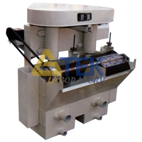
FX Model Continuous Mechanical Flotation Machine is applicable to separation of minerals with Float-free method in labs. It is a unit of several combinations of two cells with number of the cell being even, varying from two to ten cells. Left or right type flotation machine can be supplied as required by customer.
Structure
FX flotation machine is a kind of impeller mechanical flotation machine which mainly consist of cell. It is made of welded steel plate and through impeller agitation and scraping device.
1. To adjust the level of slurry in the cell and the thickness of the scraped froth layer, use wall plates of the two cells to make intermediary cell; install slurry level regulator; and mount orifice plate onto the cover in the cell to avoid negative effects on the froth zone exerted by the chaotic motion of slurry, as well as to avoid the gangue from being taken into the concentrate by the machine.
Lining plates are installed at the cell so that the bottom of the cell will not be abraded. The lining plate can be replaced. On the outside of the cell bottom is a discharge mouth, which is used to discharge water during its cleaning.
The slurry flows through the overflow mouth of wall panel into the intermediary cell and tail cell. It flows to the lower part of the intermediary cell and the duct covered by the lower part of the cell wall and then to the next cell. In this way, it can continue to flow through all the cells of flotation machine. It flows from the feed cell and is discharged from the discharge mouth of the tail cell. The front and back of the lower part of the cell is installed feeding mouth, to make it easy to change the process flow.
2. The impeller system is a disk impeller which is installed in the center of the cell in the flotation machine and whose blades are radially arranged. It is fixed onto the lower end of the impeller shaft and revolves around the vertical shaft pipe. The upper end of the pipe lies above the pulp stone and the froth layer while its lower end is supported on the cover. When the impeller rotates, a large amount of air can be sucked along the vertical pipe. Below the cover is fixed protective disk. The gap between the safety disk and the impeller depends on the amount of sucked air. It cannot be larger than 3mm at most. When the gap is too large, replace the abraded protective disc and make appropriate adjustment.
The holes in the vertical pipe are used to circulate slurry as well as mix the slurry and air. The rolling shaft installed inside the bearing shell above the impeller shaft rotates. The bearing shell is installed on the crossbeam and belt pulley is fixed on the top of the shaft which rotates through the V-belt when the motor is turned on. The tension of the V-belt is adjusted through the nuts.
3. Scraping device: The froth is scraped along the flotation machine through rotary scraper. The scraper is installed outside the discharge mouth of cell. At one end of the scraping shaft is installed belt pulley which rotates through the drive of worm reducer and V-belt.
Technical Specification
| Model | FX2-1.5 | FX2-3 | FX2-7 | FX2-12 | FX2-24 | FX2-39 | |
|---|---|---|---|---|---|---|---|
| Cell Volume (L) | 1.5 | 3 | 7 | 12 | 24 | 39 | |
| Cell Number | 2 | 2 | 2 | 2 | 2 | 2 | |
| Impeller Diameter (mm) | Φ70 | Φ70 | Φ110 | Φ130 | Φ170 | Φ200 | |
| Impeller Speed (r/min) | 1400 | 1332,1600,1836 | 1050-1320 | 700-1100 | 700-1100 | 809 | |
| Scraper Speed (r/min) | 33 | 20,30 | 15 | 15 | 15 | 13,21 | |
| Feeding Size (mm) | ≤0.2 | ≤0.2 | ≤0.2 | ≤0.2 | ≤0.2 | ≤0.2 | |
| Power (W) | 250 | 250 | 370 | 550 | 1100 | 1500 | |
| External Size |
Length (mm) | 378 | 500 | 690 | 750 | 940 | 1081 |
| Width (mm) | 406 | 500 | 560 | 600 | 680 | 762 | |
| Height (mm) | 523 | 600 | 670 | 630 | 870 | 930 | |
| Weight (kg) | 25 | 40 | 55 | 85 | 260 | 280 | |
Brochures